The utility model relates to a die casting die, in particular to a sprue system for a die casting die.
Background technology: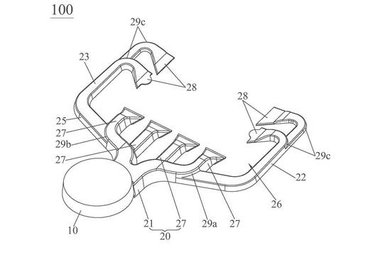
With the continuous development of economy and the continuous improvement of people's living water, it provides people with all kinds of material consumer goods, so as to enrich people's living standards.
Among them, in our daily life, we often see magnesium alloy, aluminum alloy or magnesium aluminum alloy workpieces; Because the workpiece is made of magnesium alloy, aluminum alloy or magnesium aluminum alloy, the die-casting die is often used to die-casting the workpiece.
In the process of high-pressure casting of square die-casting parts, because the sprue system of the die-casting mold includes a round platform shaped sprue riser and a sprue connected with the sprue riser, the end of the sprue directly branches out of the gate on the same side. Therefore, during high-pressure casting of square die-casting parts, the molten material from the sprue riser into the sprue flows into the forming cavity of the die-casting mold from the gate on the same side, This will make the molten material filling in the forming cavity uneven, resulting in the defects of under casting and deformation of the formed die castings.
Therefore, there is an urgent need for a sprue system for die casting die to overcome the above defects.
Technical realization elements:
The utility model aims to provide a sprue system for a die-casting die to solve the defects of under casting and deformation of square die-casting parts.
In order to achieve the above purpose, the technical scheme of the utility model is to provide a sprue system for a die casting die, which is arranged in the die casting die, including a round platform shaped pouring riser and a flow channel offset and staggered downward relative to the pouring riser. The flow channel comprises a main flow channel and a first linear flow channel and a second linear flow channel spaced and parallel to each other, the first end of the main flow channel extends directly below the pouring riser and is connected with the pouring riser, and the second end of the main flow channel obliquely branches out the first inclined flow channel and the second inclined flow channel with expanded spacing along the direction away from the pouring riser, The end of the first inclined channel is communicated with the first linear channel, the end of the second inclined channel is communicated with the second linear channel, and the first inclined channel and the second inclined channel branch out the main gate located in the space surrounded by the first inclined channel, the second inclined channel, the first linear channel and the second linear channel, Each of the first linear runner and the second linear runner branches out an auxiliary gate located in the space surrounded by the first inclined runner, the second inclined runner, the first linear runner and the second linear runner, and the extension direction of the main gate intersects with the extension direction of the auxiliary gate.
Preferably, there are two main gates on the first inclined channel and the second inclined channel respectively.
Preferably, in the first inclined channel, one of the two main gates is close to the first linear channel and the other is close to the second inclined channel, and the depth of the main gate close to the first linear channel is greater than that close to the second inclined channel.
Preferably, in the first inclined flow channel, the junction between the main gate close to the first linear flow channel and the first inclined flow channel is an arc-shaped turning structure.
Preferably, in the second inclined channel, one of the two main gates is close to the second linear channel and the other is close to the first inclined channel, and the depth of the main gate close to the second linear channel is greater than the depth of the main gate close to the first inclined channel.
Preferably, in the second inclined flow channel, the junction between the main gate close to the second linear flow channel and the second inclined flow channel is an arc-shaped turning structure.
Preferably, there are two auxiliary gates on the first linear channel and the second linear channel respectively.
Preferably, in the first linear channel, one of the two auxiliary gates is close to the first inclined channel and the other is far away from the first inclined channel, and the depth of the auxiliary gate close to the first inclined channel is greater than that away from the first inclined channel.
Preferably, in the second straight channel, one of the two auxiliary gates is close to the second inclined channel and the other is far away from the second inclined channel, and the depth of the auxiliary gate close to the second inclined channel is greater than that away from the second inclined channel.
Preferably, the junction between the first linear runner and the auxiliary gate and the junction between the second linear runner and the auxiliary gate are arc-shaped turning structures.
Compared with the prior art, the second end of the main runner of the utility model obliquely branches out the first inclined runner and the second inclined runner with expanded spacing along the direction away from the pouring riser, the end of the first inclined runner is connected with the first linear runner, and the end of the second inclined runner is connected with the second linear runner, The first inclined channel and the second inclined channel branch out the main gate in the space surrounded by the first inclined channel, the second inclined channel, the first linear channel and the second linear channel, and the first linear channel and the second linear channel branch out the auxiliary gate in the space surrounded by the first inclined channel, the second inclined channel, the first linear channel and the second linear channel, The extension direction of the main gate intersects with that of the auxiliary gate; Therefore, under the action of the main gate and auxiliary gate, the molten material is fed and filled from three sides to the forming cavity of the die-casting die, so as to make the feeding in the forming cavity of the die-casting die uniform, so as to solve the defects of under casting and deformation of square die-casting parts.